
How oxyhydrogen helps your diesel engine burn its fuel
Your diesel engine already does the heavy lifting. A Hydroxi Oxyhydrogen fuel generator helps it get more work out of the fuel you pay for. It works on the combustion itself: how quickly and how completely the diesel burns inside the cylinder.
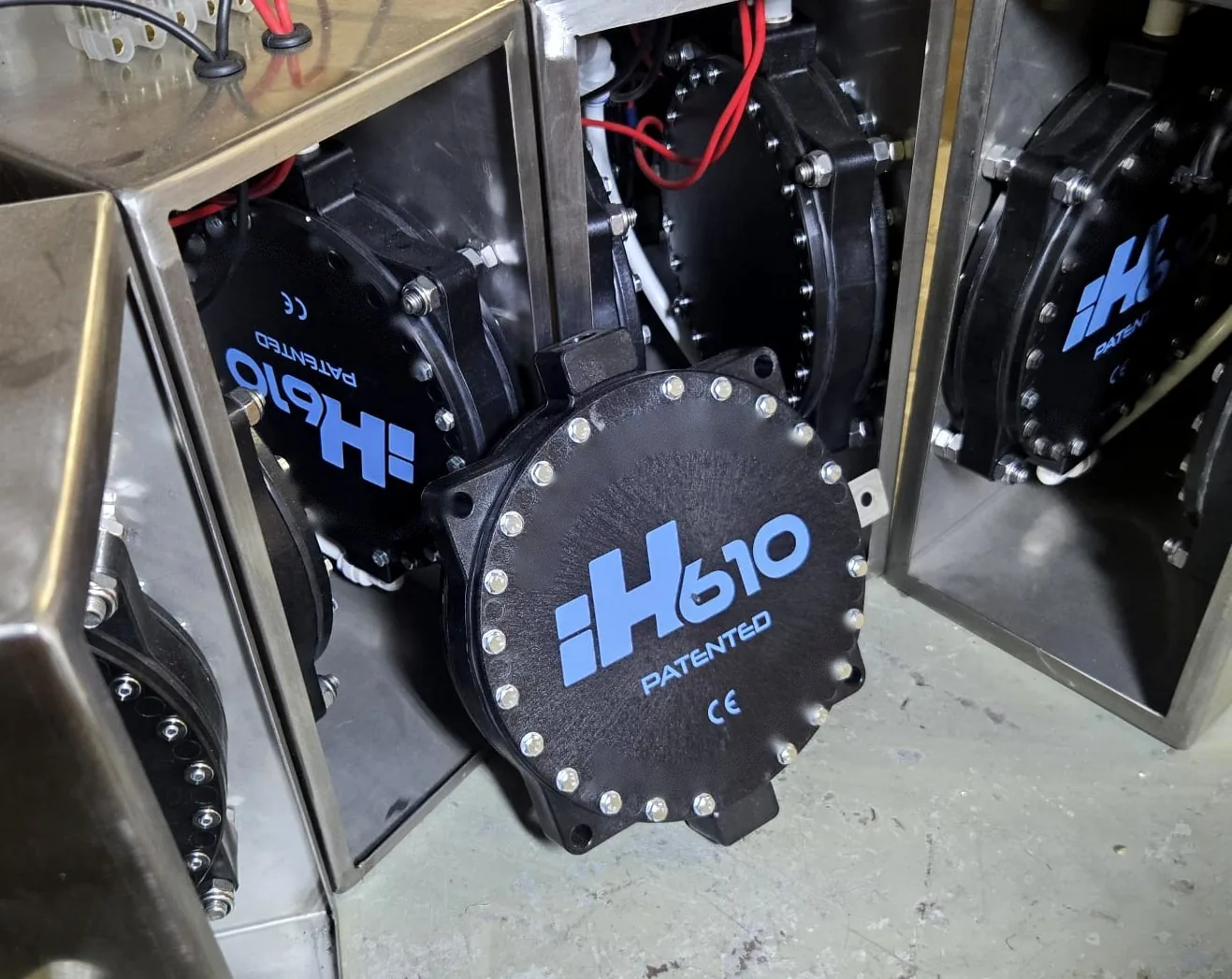
Here is how it works, what it can do for your trucks, buses and generators, and where its limits are.
How it works, step by step
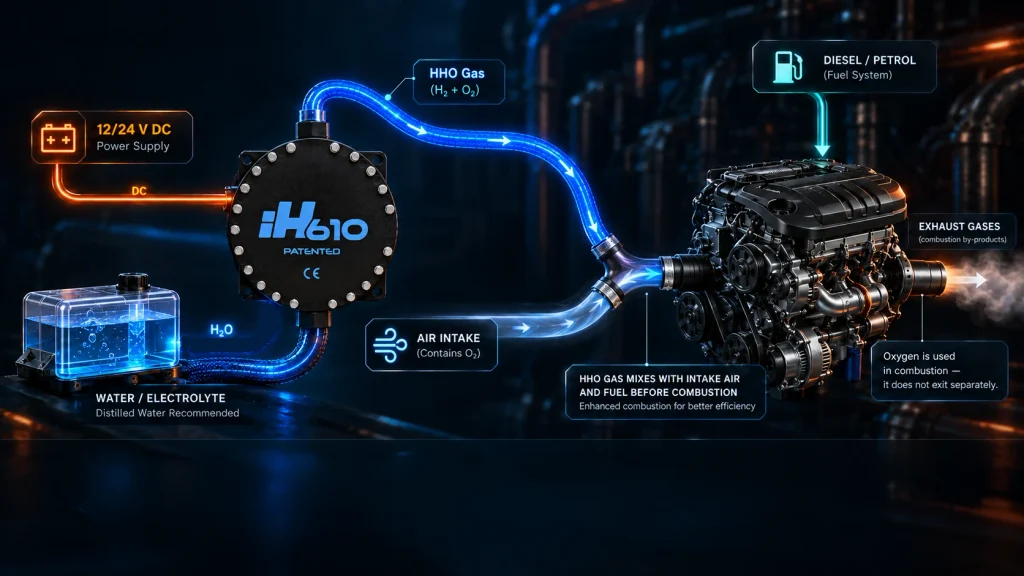
- Power from your battery. While the engine runs, the Oxyhydrogen fuel generator draws a small electrical current from the vehicle’s battery, which the alternator keeps charged.
- Water is split. Inside the unit, that current passes through distilled water mixed with an electrolyte. Electrolysis splits the water into hydrogen and oxygen. Together they form oxyhydrogen, often known as HHO.
- Made on demand, nothing stored. The gas is made only while the engine runs and is used straight away. No gas is stored on the vehicle. A controller switches the system on and off with the engine.
- Into the air intake. The gas flows through a small connection to the engine’s air intake. There it mixes with the intake air to form an Air/Oxyhydrogen mixture, which then meets the diesel charge in the cylinder.
- A faster, more complete burn. Hydrogen burns with a faster flame speed than a normal fuel-air mixture. In the cylinder, the Air/Oxyhydrogen mixture ignites easily, which helps the diesel burn faster and more completely.
What it can do for your vehicles
More work from the diesel you buy
When more of each fuel charge burns completely, the engine can do the same work with less diesel. That’s how oxyhydrogen can help fuel economy, and for a fleet it goes straight to operating costs.
Smoother, more responsive running
Because the Air/Oxyhydrogen mixture ignites easily, combustion can be more even from one stroke to the next. The engine can feel smoother and more responsive under load.
Less carbon build-up, less wear
A cleaner burn leaves less carbon behind, because hydrogen contains no carbon. Over time, this can help reduce deposits inside the engine and the wear they cause on parts such as valves and pistons.
Lower emissions, from the cylinder
More complete combustion can mean cleaner exhaust with less soot. Using less diesel for the same work also means less CO2 for that work. Our Research page shows what has been measured, and how.
How it fits alongside SCR, AdBlue and your DPF
SCR uses AdBlue to treat nitrogen oxides in the exhaust, and a diesel particulate filter (DPF) traps soot. Both clean up the exhaust after combustion. Oxyhydrogen works one step earlier, in the cylinder. It complements your after-treatment rather than replacing it, and we don’t touch your SCR or DPF. Those systems can simply receive cleaner exhaust to deal with.
- In the cylinderCombustionOxyhydrogen works here
- ExhaustSCR + AdBlueTreats nitrogen oxides
- ExhaustDPFTraps soot
What is HHO?
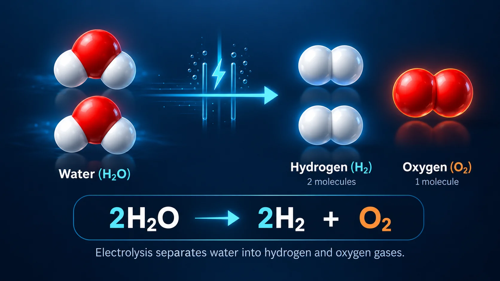
HHO, also called oxyhydrogen, is a mixture of hydrogen and oxygen gas made by passing an electric current through water. This process is called electrolysis: 2H₂O → 2H₂ + O₂. Every two molecules of water give two molecules of hydrogen and one of oxygen. HHO is a gas mixture, not a single “HHO” molecule. Hydrogen is flammable across a wide range of concentrations and burns once it reaches its self-ignition temperature. That is why the Hydroxi System makes the gas on demand, only while the system is running, instead of storing it.
Inside the cell
Inside the cell: how the gas is generated
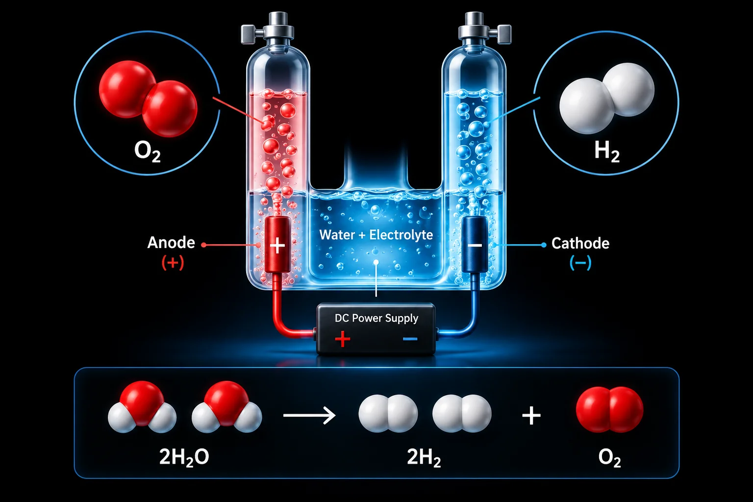
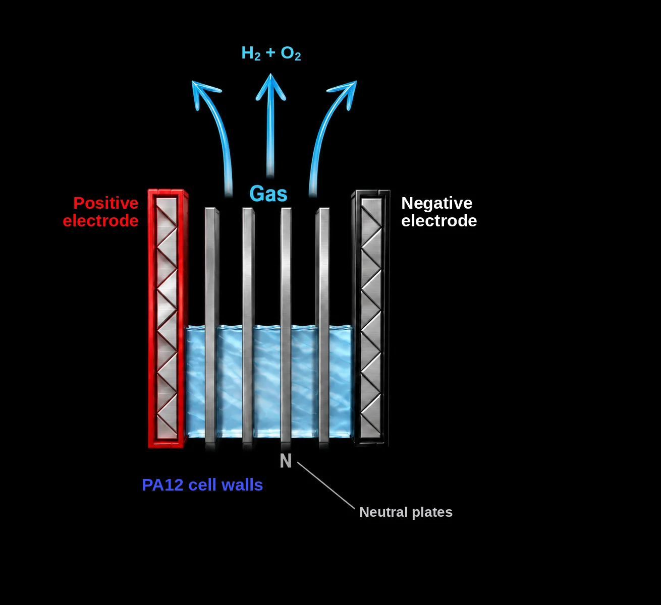
The cell has a positive electrode (anode), a negative electrode (cathode) and, between them, a set of neutral plates marked N. The neutral plates aren’t wired to anything. When the two electrodes are energised, each neutral plate takes on a negative charge on one face and a positive charge on the other. The cell then works as a row of smaller cells side by side, with hydrogen forming on the negative faces and oxygen on the positive faces.
Pure water conducts electricity poorly, so a small, controlled amount of potassium hydroxide (KOH) is dissolved in the distilled water before it goes into the tank. This electrolyte lets the current pass through the water.
Current through each cell is held at about 6 to 7 amps. Keeping it there avoids an unnecessary rise in temperature and supports a consistent, good-quality gas output. The cell walls are made of PA12, a semi-crystalline thermoplastic.
Cell design
Why cell design matters
Electrolysis is simple in principle. Doing it consistently, hour after hour in an engine bay, depends on how the cell is built.
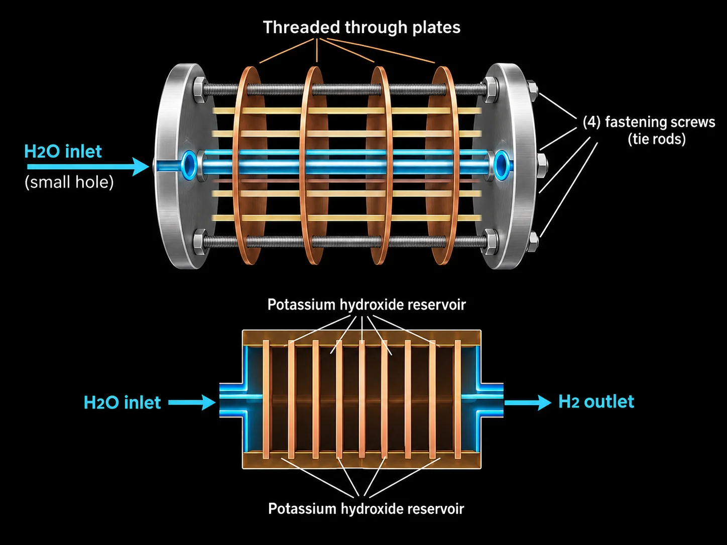
In many conventional cells, water enters through a single small tube, and the shape of the plates leaves pockets where the potassium hydroxide solution sits still instead of circulating. These stagnant pockets heat up, and the extra heat produces more water vapour. The result is that water vapour is carried along with the hydrogen into the engine’s intake duct, instead of clean gas.
Many of these cells are also built as a stack of plates clamped together with tie rods, and the stack has to stay perfectly aligned to avoid leaks.
The Hydroxi cell needs relatively little electrolyte to keep gas production steady.
Manufacturer testing
Thermal analysis of the iH610 HHO cell
Stagnation inside a cell shows up as heat, because trapped electrolyte and gas raise the temperature locally. To check for it, the manufacturer ran a thermographic analysis on a prototype of the iH610 HHO cell after 4 hours of operation at 14.8 V and 20 A, using a FLIR 440BX thermal camera. The table shows the readings at five points. They sit within 0.5 °C of each other, which shows an even internal temperature, and no stagnation zones were detected.
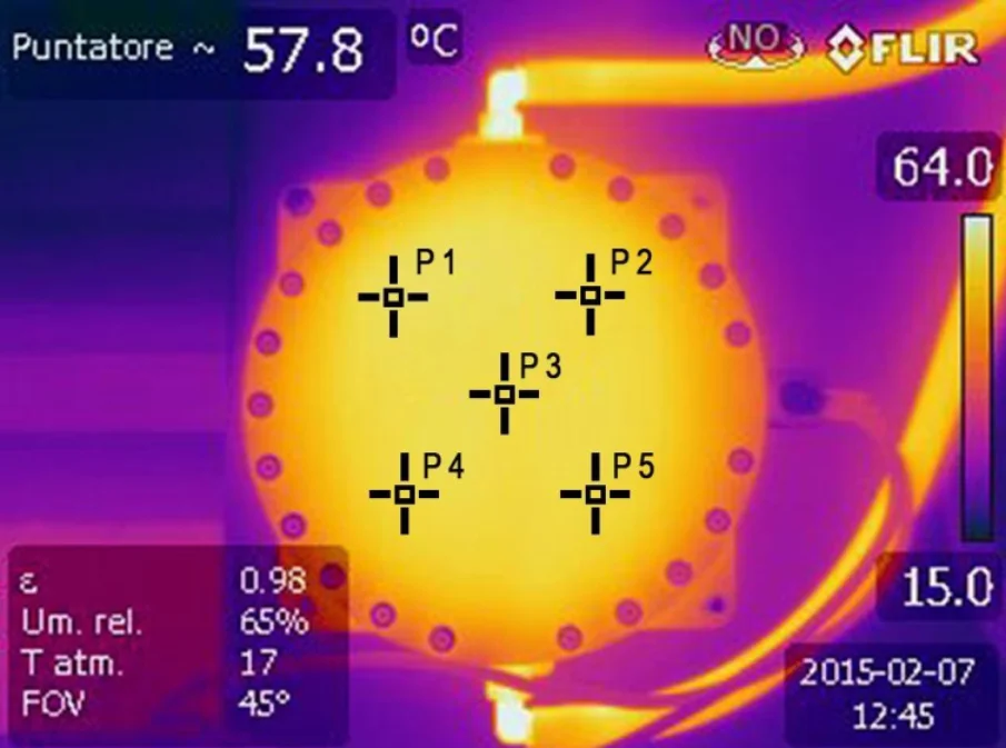
| Measured point | Temperature |
|---|---|
| P1 | 57.4 °C |
| P2 | 57.3 °C |
| P3 | 57.8 °C |
| P4 | 57.5 °C |
| P5 | 57.4 °C |
FLIR thermal image of a prototype iH610 cell after 4 hours at 14.8 V / 20 A. Ambient temperature 17 °C, 7 February 2015. Manufacturer-reported test.
Configuration
Set up for your engine
Every engine draws a different volume of air. A four-stroke engine takes in roughly half its displacement for every revolution – a 2-litre engine at 3,000 rpm draws about 3 m³ of air a minute. That is why the system is configured per engine: the electrolyte concentration is set during installation to reach the current and gas output the specific engine needs.
Not sure whether your engine qualifies? Verify Compatibility before you go further.
Specification
Technical specification
| Item | Specification |
|---|---|
| Type | Electrochemical oxyhydrogen (H₂ + O₂) cell – water electrolysis |
| Electrolyte | Potassium hydroxide (KOH), dissolved in distilled water before filling. Sodium hydroxide (NaOH) is an alternative listed by the manufacturer. |
| Electrolyte concentration | Set at installation to reach the current/output required for the engine |
| Reservoir fill level | About half full; never above 50–60% |
| Materials, dimensions, mass, current range | [Content to come] |